
How to Jog the Robot
This is an example of how to Jog the Robot Manually using the Move Screen
Examples are valid for:
CB3 Software Version: 3.3.3.292
Note that older or newer software versions may behave differently.
These examples can be used for both CB2 and for CB3/CB3.1.

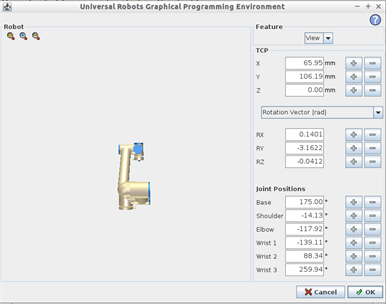
Figure 1 – Move Screen
1) Robot
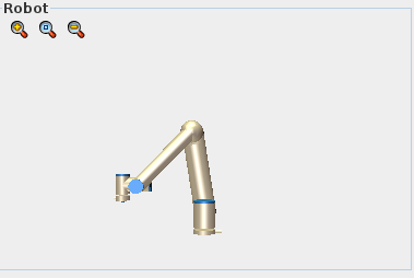
Figure 2 – Robot
The Robot window (Figure 2) on the Move Screen shows the robots current position. The simulated robot moves around in real-time with the real robot. The magnifying glass icons can be used to zoom in or out. Dragging a finger across the view will manipulate the simulated robot. This can be used to position the robot’s arm in the “View” feature to how the robot appears to the operator thus allowing them to manipulate using the Move Tool.
2) FEATYRE/TCP
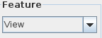
Figure 3 – Feature Selection
The Feature window (Figure3) allows you to change the robot’s coordinate system. There are three (3) default coordinate systems:
- Base
- Orients +Y aligning to the robot cable
- Tool
- Orients -Y aligning to the Tool I/O Connector
- View
- Allows for Orientation to be determined by Operator
Additional features can be created (in the Installation tab) and then be selected within the Feature window and used on the Move Screen.
 |
 |
|
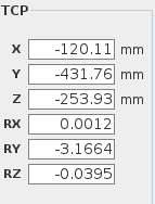
Figure 4 – TCP Window |
Figure 5 – TCP Editor Screen |
The TCP Window (Figure 4) allows the operator to manipulate the robot using coordinates with XYZ being in millimeters (mm) and RX-RY-RZ being in radians (rad). Using the TCP Editor Screen (Figure 5) the robot can be manipulated by adding or subtracting to any of the above coordinates as well as the joint positions.
3) MOve Joints

Figure 6 – Move Joints
Using the Move Joints Window (Figure 6) the individual joints of the robot can be manipulated. By holding onto the arrows that individual joint will rotate. The tick marks show where the robot is presently within it’s +/- 360° rotation, these values update in real time. The numerical values next to each joint location represent the tick mark’s current location in degrees.
4) Move tool
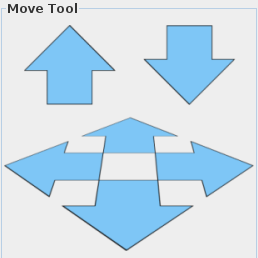
Figure 7 – Translational Arrows
Holding down one of the translational arrows (Figure 7) will move the robot in the direction indicated. This is based on the coordinate system. Releasing the button at any time stops the motion of the robot.
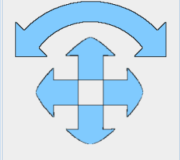
Figure 8 – Rotational Arrows
Holding down one of the rotational arrows (Figure 8) will change the orientation of the robot tool in the indicated direction. The point around which the robot will move is the TCP. Releasing the button at any time stops the motion of the robot.
5) Home
| |
 |
|
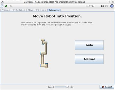
Figure 9 – Home Button |
Figure 10 – Move Into Position |
The Home Button (Figure 9) will enter the Move into Position screen (Figure 10). This allows the robot to be positioned, from any orientation, into its home (or Vertical) position.
6) freedrive
| |
 |
|
Figure 11 – Freedrive Button (Screen) |
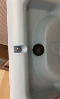
Figure 12 – Freedrive Button (Back of Pendant) |
Freedrive allows the robot to be manipulated by hand; to activate Freedrive press and hold the button on the screen (Figure 11) or on the back of the Teach Pendant (Figure 12). Additional I/O can be added to allow an operator to enter Freedrive Mode.